DIY Arduino Based Air Sensor (pt. 2)
Happy new year!! 🎊
This blog is part 2 of a series of projects where we'll be building an air sensor on the arduino platform. In part 2, we'll build upon the basic air sensor setup introduced in part 1 by introducing a sleep and wake functionality to prolong the life of the sensor.
hardware
- same as part 1
software
- same as part 1
useful links
1. let's get connected
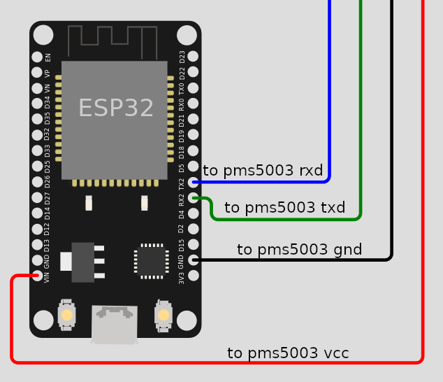
This is mostly the same as the part 1 wiring digram, with the addition of the connection "to pms5003 rxd (blue wire)". The connection will allow the ESP32 to send sleep and wake commands to the PMS5003 sensor.
2. code it out
#include "Adafruit_PM25AQI.h"

Adafruit_PM25AQI sensor = Adafruit_PM25AQI();

void setup() {
  Serial.begin(115200);
  // Since the sensor is connected to the RX2 and TX2 pin, we will use Serial2 to send and receive values.
  Serial2.begin(9600);
  sensor.begin_UART(&Serial2);
}

void loop() {
  PM25_AQI_Data data;
  if (sensor.read(&data)) {
    Serial.print("PM2.5: ");
    Serial.print(data.pm25_standard);
    Serial.print("\n\n");

    Serial.print("Sleeping sensor for 15 mins...");
    Serial.print("\n\n");
    sleepSensor();
    delay(60000 * 15);

    Serial.print("Waking sensor...");
    Serial.print("\n\n");
    wakeSensor();
    activeSensor();
    // Per the manual, we need to wait 30 seconds after waking up the sensor for more stable data.
    delay(30000);
  } else {
    delay(1000);
  }
}

void sleepSensor() {
  uint8_t sleep[] = {0x42, 0x4D, 0xE4, 0x00, 0x00, 0x01, 0x73};
  Serial2.write(sleep, sizeof((sleep)));
}

void wakeSensor() {
  uint8_t wake[] = {0x42, 0x4D, 0xE4, 0x00, 0x01, 0x01, 0x74};
  Serial2.write(wake, sizeof((wake)));
}

void activeSensor() {
  uint8_t active[] = {0x42, 0x4D, 0xE1, 0x00, 0x01, 0x01, 0x71};
  Serial2.write(active, sizeof((active)));
}
Checkout the pms5003 manual for other commands and options. The ones we're interested in for the purposes of this tutorial are sleep, wake, and active.
void sleepSensor() {
  uint8_t sleep[] = {
    /*constant*/0x42,
    /*constant*/0x4D,
    /*command*/ 0xE4,
    /*constant*/0x00,
    /*option*/ 0x00,
    /*higher validation byte*/0x01,
    /*lower validation byte*/0x73
  };
  Serial2.write(sleep, sizeof((sleep)));
}

void wakeSensor() {
  uint8_t wake[] = {0x42, 0x4D, 0xE4, 0x00, 0x01, 0x01, 0x74};
  Serial2.write(wake, sizeof((wake)));
}

void activeSensor() {
  uint8_t active[] = {0x42, 0x4D, 0xE1, 0x00, 0x01, 0x01, 0x71};
  Serial2.write(active, sizeof((active)));
}
-
The first couple bytes (1st, 2nd) are constant startup bytes.
-
The 3rd byte in each sequence corresponds to the command.
-
The fourth byte is also constant.
-
The 5th byte is a flag for "options" we can attach to the command. For example, sleep and wake have the same
0xe4command byte, but different options -0x00for sleep and0x01for wake. -
The last couple of bytes (6th, 7th) are validation bytes. To get these values, we add up the previous bytes and represent them across a higher byte and lower byte.
-
Take the sleep command for example:
0x42 + 0x4D + 0xE4 + 0x00 + 0x00=0x173. The 6th validation byte is0x01and the 7th validation byte is0x73.
3. upload the code and open serial monitor
With the code running on the microcontroller, pull up the serial monitor at a baud rate of 115200 and observe the values. It should look something like this.
Also inspect the sensor itself to verify that sleep and wake are working properly. The sensor's fan should stop spinning on sleep and restart spinning on wake.
PM2.5: 20

Sleeping sensor for 15 mins...

Waking sensor...

PM2.5: 20

...
4. next steps
In the next part of this series, we'll add a temperature and humidity sensor to augment the capability of our air sensor. Stay tuned!